- 您现在的位置:买卖IC网 > Sheet目录3871 > PIC16F72-I/ML (Microchip Technology)IC PIC MCU FLASH 2KX14 28-QFN
103
2535J–AVR–08/10
ATtiny13
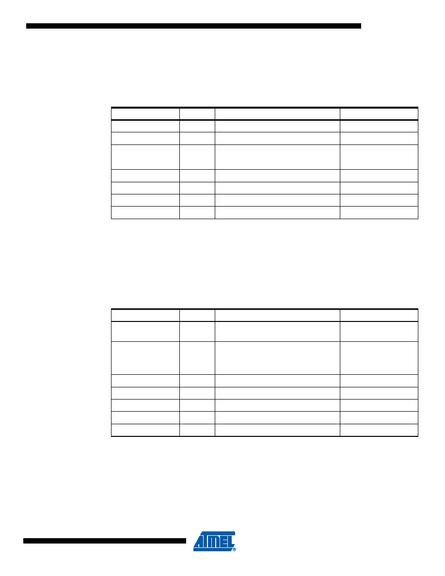
17.2 Fuse Bytes
The ATtiny13 has two fuse bytes. Table 17-3 on page 103 and Table 17-4 on page 103 describe
briefly the functionality of all the fuses and how they are mapped into the fuse bytes. Note that
the fuses are read as logical zero, “0”, if they are programmed.
Notes: 1. Enables SPM instruction. See “Self-Programming the Flash” on page 97.
2. DWEN must be unprogrammed when lock Bit security is required. See “Program And Data
3. See Table 18-5 on page 119 for BODLEVEL fuse decoding.
4. See “Alternate Functions of Port B” on page 54 for description of RSTDISBL and DWEN fuses.
When programming the RSTDISBL fuse, High-voltage Serial programming has to be used to
change fuses to perform further programming.
Notes: 1. The SPIEN fuse is not accessible in SPI Programming mode.
2. Programming this fues will disable the Watchdog Timer Interrupt. See “Watchdog Timer” on
page 37 for details.
3. See “System Clock Prescaler” on page 26 for details.
4. The default value of SUT1..0 results in maximum start-up time for the default clock source.
See Table 18-3 on page 118 for details.
5. The default setting of CKSEL1..0 results in internal RC Oscillator @ 9.6 MHz. See Table 18-3
on page 118 for details.
Table 17-3.
Fuse High Byte
Fuse Bit
Bit No
Description
Default Value
–
7
–
1 (unprogrammed)
–
6
–
1 (unprogrammed)
–
5
–
1 (unprogrammed)
4
Self Programming Enable
1 (unprogrammed)
DWEN(2)
3
debugWire Enable
1 (unprogrammed)
2
Brown-out Detector trigger level
1 (unprogrammed)
1
Brown-out Detector trigger level
1 (unprogrammed)
0
External Reset disable
1 (unprogrammed)
Table 17-4.
Fuse Low Byte
Fuse Bit
Bit No
Description
Default Value
SPIEN(1)
7
Enable Serial Programming and Data
Downloading
0 (programmed)
(SPI prog. enabled)
EESAVE
6
Preserve EEPROM memory through
Chip Erase
1 (unprogrammed)
(memory not preserved)
WDTON(2)
5
Watchdog Timer always on
1 (unprogrammed)
4
Divide clock by 8
0 (programmed)
3
Select start-up time
1 (unprogrammed)
2
Select start-up time
0 (programmed)
1
Select Clock source
1 (unprogrammed)
0
Select Clock source
0 (programmed)
发布紧急采购,3分钟左右您将得到回复。
相关PDF资料
XF2R34154A
CONN FPC 34POS 0.5MM PITCH SMD
XF2R24154A
CONN FPC 24POS 0.5MM PITCH SMD
PIC18F45K20-I/ML
IC PIC MCU FLASH 16KX16 44QFN
PIC18F14K50-I/SO
IC PIC MCU FLASH 8KX16 20-SOIC
PIC16F628A-I/SS
IC MCU FLASH 2KX14 EEPROM 20SSOP
PIC18LF43K22-I/PT
IC PIC MCU 8KB FLASH 44TQFP
DSPIC33FJ16MC101-I/SO
IC DSP 16BIT 16KB 20SOIC
PIC12C672-04I/SM
IC MCU OTP 2KX14 A/D 8-SOIJ
相关代理商/技术参数
PIC16F72-I/MLG
功能描述:8位微控制器 -MCU 3.5KB 128 RAM 22 I/O Lead Free Package RoHS:否 制造商:Silicon Labs 核心:8051 处理器系列:C8051F39x 数据总线宽度:8 bit 最大时钟频率:50 MHz 程序存储器大小:16 KB 数据 RAM 大小:1 KB 片上 ADC:Yes 工作电源电压:1.8 V to 3.6 V 工作温度范围:- 40 C to + 105 C 封装 / 箱体:QFN-20 安装风格:SMD/SMT
PIC16F72-I/SO
功能描述:8位微控制器 -MCU 3.5KB 128 RAM 22 I/O
RoHS:否 制造商:Silicon Labs 核心:8051 处理器系列:C8051F39x 数据总线宽度:8 bit 最大时钟频率:50 MHz 程序存储器大小:16 KB 数据 RAM 大小:1 KB 片上 ADC:Yes 工作电源电压:1.8 V to 3.6 V 工作温度范围:- 40 C to + 105 C 封装 / 箱体:QFN-20 安装风格:SMD/SMT
PIC16F72-I/SO
制造商:Microchip Technology Inc 功能描述:8BIT FLASH MCU SMD 16F72 SOIC28
PIC16F72-I/SOG
功能描述:8位微控制器 -MCU 3.5KB 128 RAM 22 I/O Lead Free Package RoHS:否 制造商:Silicon Labs 核心:8051 处理器系列:C8051F39x 数据总线宽度:8 bit 最大时钟频率:50 MHz 程序存储器大小:16 KB 数据 RAM 大小:1 KB 片上 ADC:Yes 工作电源电压:1.8 V to 3.6 V 工作温度范围:- 40 C to + 105 C 封装 / 箱体:QFN-20 安装风格:SMD/SMT
PIC16F72-I/SP
功能描述:8位微控制器 -MCU 3.5KB 128 RAM 22 I/O
RoHS:否 制造商:Silicon Labs 核心:8051 处理器系列:C8051F39x 数据总线宽度:8 bit 最大时钟频率:50 MHz 程序存储器大小:16 KB 数据 RAM 大小:1 KB 片上 ADC:Yes 工作电源电压:1.8 V to 3.6 V 工作温度范围:- 40 C to + 105 C 封装 / 箱体:QFN-20 安装风格:SMD/SMT
PIC16F72-I/SP
制造商:Microchip Technology Inc 功能描述:IC 8BIT FLASH MCU 16F72 SDIL28
PIC16F72-I/SS
功能描述:8位微控制器 -MCU 3.5KB 128 RAM 22 I/O
RoHS:否 制造商:Silicon Labs 核心:8051 处理器系列:C8051F39x 数据总线宽度:8 bit 最大时钟频率:50 MHz 程序存储器大小:16 KB 数据 RAM 大小:1 KB 片上 ADC:Yes 工作电源电压:1.8 V to 3.6 V 工作温度范围:- 40 C to + 105 C 封装 / 箱体:QFN-20 安装风格:SMD/SMT
PIC16F72-I/SS
制造商:Microchip Technology Inc 功能描述:8BIT FLASH MCU SMD 16F72 SSOP28